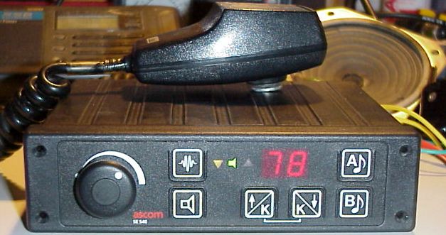
This transceiver exists in different versions for different frequency bands. It seems that they were also known under the name Condor Standard. It has 20 channels, freely programmable, also with shift for trafic via repeater.
Different model variant exist, see numbering_scheme
Some remarks
- Honestly it’s not a great radio for general amateur usage, but it’s amazing to use a rig that you’ve modified yourself.
- Usage example: program it for the local QRG or repeater, and you can keep your main station free to look for DX, while still watching the local activity
- A bad « feature » of this radio, is that it is sensitive to ignition noise, when mounted in a vehicle. This noise is transmitted along with the modulation of the operator. It may be a good idea to add a filter in the power cables, to remove this small drawback.
- The VCO’s of the UHF version can hardly cover the whole 430-440 MHz. It’s limited to about 5-7 MHz. For repeater operation only this is not a problem.
I found all documentation on the Internet. The most comprehensive sites about this radio are (as far as I know):
- The excellent site of F5JTZ about the SE-540 (french)
- PE1PSA’s site and PE7TWO wo used to have websites about this radio, but which are not online anymore unfortunatley
I have modified several SE-540 for amateur use, working on VHF and UHF. Unfortunately most websites and tools I used are not online anymore…
It starts by using the IPP540 programmer. Edit the differents fields (frequency and other stuff) and save the datas in a *.DAT file. The program is in Dutch language, so this is funny:-) Read the help (F1 key) it’s in German.
Then you needed to convert the file *.DAT file to a « burnable » binary EPROM file (*.bin), using PE1PSA’s online converter. After that, burn the EPROM, and proceed to the tuning, as explained on PE1PSA’s or F5JTZ’s sites. Hint: use the IPP540 programm in a folder named c:\ipp540\ or this old DOS programm have some problems at runtime.
UHF Version
I’ve modified one radio with 10W output power, and another one which has 20W.
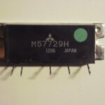
The 10W version worked fine, but on the 20W one, I had to change the power amplifier. The installed « brick » was a M57729H, which is designed for frequencies between 450 and 470 Mhz. I replaced it with a M57729, which works fine between 430 and 440 MHz. This change is not so easy to do, because you have to unsolder the whole metal plate which acts as shielding on the printed circuit board. I used a 100W soldering iron to do the job.
Have look at the measurement I made of the M57729H module, you will see that frequency range of interest is a little bit « out band ». As the driver is not too strong, the reult is a very small output power between 430 and 440 Mhz. That’s why you need to change the module. Bad news it’s obsolete now….
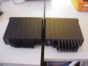
On the picture on the right, you can see the dissipator size difference between the 10W (left) and 20W (right). This is an easy way to estimate the power of the rig. If you want to be sure, you have to decrypt the type number of the radio, normally written on a label. F5JTZ explains it very clearly on his site.
If you want to use the rig, you can download directly an EPROM binary file, which contains some repeater channels used near Neuchâtel, plus three frequencies in the 430 MHz, simplex. You can also download a test EPROM file, with 20 frequencies each 500 kHz between 430 and 440 MHz, in order to tune the rig.
Be careful, the frequencies written in the *.txt file may not be exact, due to a small software problem during the conversion. They may be ±12.5 kHz right. But you will find them easily with a second receiver. Biaries and TXT contents available as ZIP file
VHF version
You have top check the HF head in the reception path. F5JTZ explains the small adjustments that have to be made. Be carefull to solder the W101-W105, otherwise the sensitivity will be VERY BAD! Some of the radios that I’ve modified had already the solder bridges in place. On one rig I had to solder them, and it worked without even changing the condensator on the 2nd helix filter to 12 pF.
Numbering scheme
Ascom SE-Serie Radio Model Number
Gerätebezeichnungssystematik für tragbare und mobile Funkgeräte ab 1.1.92 SE-XXX-XXX-X-XXXXX-X..
Example SE-160-082-2
| Typ | Freq. Band | TX Power | Channel Spacing | Model Variation | Option | |
| SE | 160 | 08 | 2 | 2 | S | |
| ^ | ^ | ^ | ^ | ^ | ||
| 110=SE110 | 04=33..45MHz | 0=driver only | 1=12.5kHz | S = Standard | ||
| 140=SE140 | 05=45..58 MHz | 1= 1.0 W | 2=20/25kHz | E = SBB with Keyboard | ||
| 160=SE160 | 08=68..88 MHz | 2= 2.5 W | 3= 25.0 kHz | C = Crypto | ||
| 540=SE540 | 14=132..148 MHz | 5= 5.0 W | 5 = 50.0 kHz | D = Digital | ||
| 550=SE550 | 16=146..174 MHZ | 6= 6.0 W | T = Trunking | |||
| 660=SE660 | 20=173..224 MHz | 7= 10.0 W | X = EEX | |||
| 21=205..207 MHz | 8= 15.0 W | CT = Crypto-Trunking | ||||
| 33=300..344 MHz | 9= 25.0 W | DT = Digital-Trunking | ||||
| 42=400..425 MHz | 10=10 W | EC = SBB with Keyboard + Crypto | ||||
| 43=400..440 MHz | 20=20W | ET = SBB with Keyboard + Trunking | ||||
| 45=425..450 MHz | 25=25W | TX = Trunking + EEx Achtung : Subfrequenzbereich 147-156 MHZ !! | ||||
| 46=430..470 MHz | Teco = Trunking + low grade | |||||
| 47=450..470 MHz | Seco = standard + low grade (SE660) | |||||
| 92=892..980 MHz | TXeco = Trunking + Ex + low grade |
This table comes from http://www.oppermann-telekom.de/se160-modelle.html