Thanks to OM Felix, DG1YFE, who kindly provided me his excellent Firmware and informations about the radio, I was able to get it work on the amateur VHF band.
EEPROM
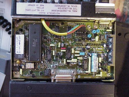
To use DG1YFE’s firmware, the radio must have an external EPROM (27C128 minimum) aside the CPU (HD63A03YP). On the picture, the EPROM is the integrated circuit with the white sticker on top of it. My radio is an EVA9 model, but there are other firmware versions available. If the CPU has an integrated OTPROM it’s not possible to use this firmware. In this case you can stop reading this webpage here.
Firmware
The firmware for this radio has been re-written by DG1YFE, OM Felix. I don’t provide it here, please ask the author directly. Contact information here. Use a standard EPROM programmer to burn it. If you don’t own such a device, ask the local ham community. There will surely be someone who can programm the EPROM for you.
VCO tuning
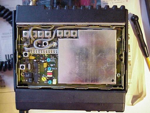
The radio you have is probably running on the professional band, slightly above the amateur band. You need to adjust the VCO’s. If you use Felix’ software, the RED LED is a valuable companion for this phase. Tune the radio on 145.000 (center of the band for EU). Start by screwing down the RX coil (Yellow component on the top right of the picture below) until the RED LED vanishes. Try to find the middle position so that the setting is centered at 145.000. Check at 144.000 and 146.000 MHz whether the RX PLL is locked (RED LED not visible).
Do the same for the TX VCO (Red coil). Be sure to connect the radio to a dummy load, because you may need to transmit for a long time until you’ve found the best setting

Alignment
The front end filters have to be aligned properly in order to work on the amateur band. Otherwise the radio will be totally deaf. Adjust the 7 filters that are placed in an horizontal row, visible on top of this image.
The best to do this is to have access to an RF generator whose level can be swept. Set it to the center frequency, and FM deviation 3kHz. Start with a level that is high enough to be heard (-50 dBm should be a good value, maybe even more), and adjust the 7 filters for best reception. Then reduce the generator level in order to be just above the noise, tune again the filters, and so on until you are at the lowest possible RF level, and any tuning doesn’t improve the received audio anymore. You should end up with an RF value below -110 dBm. The less, the better.
If you don’t have access to such a generator, you can also work with a handheld transceiver. Use is at lowest possible power. To reduce the level, try to use bad antennas (just a small piece of copper un the BNC connector of the Motorola radio), and/or augment the distance between both radios.
Tips and tricks
- On one particular radio exemplar, I could get the sensitivity down to -115 dBm without noticeable « FM clicks ». Squelch opens at -118 dBm and closes at -120 dBm. These figure may be somewhat different depending on the quality of the tuning.
- The original microphone is a dynamic one with integrated preamplifier. A DC voltage is present on the same pin as Audio IN (Pin 6 of the SUB-D connector). So a standard dynamic microphone with amplifier won’t work.
- A 1750Hz is transmitted for 1 second if you press the 3rd button from the left, under the LCD display. If you need more than 1 second, in order to open a lazy repeater, just press several times the key, to maintain the 1750 Hz transmission.
- Some radios have unfortunately a depleted keyboard. In my case the front pannel PCB was fully working, only some mechanical parts of the keys were absent. I took some plastic parts on unusable radios (EZA9) to fulfill the missing keys.
- The power level can be changed between 2 levels (HI/LO) from the front panel. Each of these 2 levels can be adjusted with trimpots on the bottom side of the main PCB
3D printable connectors
Courtesy Gareth Blades