Introduction
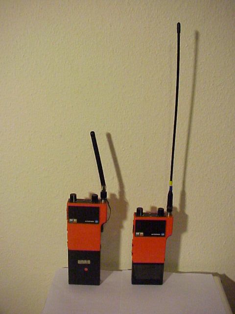
This is a famous radio (at least in Switzerland), because it was heavily used by the polices, rescue services, fire brigades,… The basic version has 3 channels. They have been used on VHF and UHF professional bands. I got the opportunity to find two very cheap units at the biggest Swiss Surplus Party in Zofingen many years ago.
The transceiver exists in different versions. On this picture you can see at least two accumulators and two antennas. Both are working on VHF.
The working frequency is defined by a quartz. In my case (but it may not be the case for all versions), the carrier frequency is calculated as follow: Frf=(2*Fquartz)+21.4 MHz
These are 3rd Overtone Crystals, which I ordered from TELCONA, with a serial resistance of less than 25 Ohms and they worked well.
Version ready for working via a repeater might require to change the whole modulator block.
Front panel
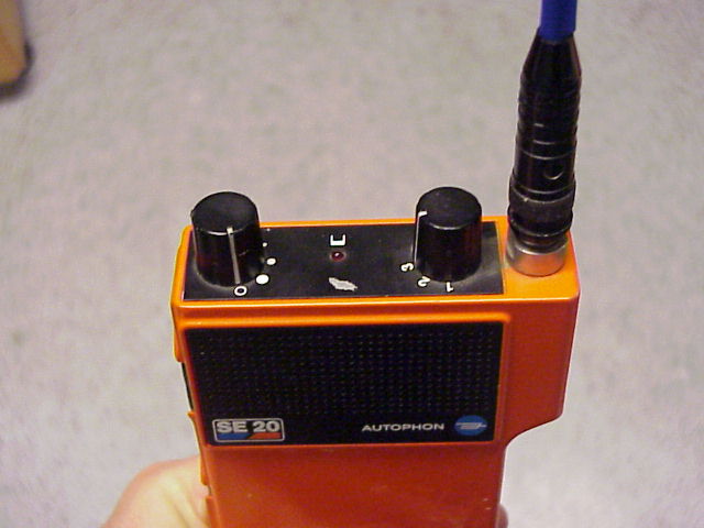
The front (top) panel is very very very simple. The ON/OFF and volume is controlled by the button on the left.
Position 0 is OFF, and a big « dot » corresponds to a high audio volume. The most conterclockwise position is marked S (not visible on the picture) and corresponds to an open squelch position. (With fixed, maximum audio level).
The 3 channels are selected by turning the button on the right.
Internal life and repair
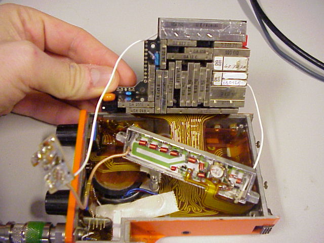
This is a view inside the transceiver. You can see the modular construction. The two metal cans with the white stickers contains the three crystals for the RF channels. One block (marked DG03) contains the oscillator, plus the cristal for Channel 1. The other block (DE01) contains the two quartz for channel 2 and 3.
The Power Amplifier has been opened, because I suspected that it was out of order. But that wasn’t the case finally.
Below is a detailed view of the PA. I had to unsolder the lid, for checking that the PA was working well! So I took the foto, not to have done all this job for nothing…
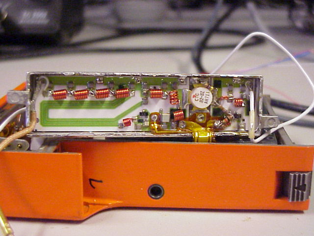
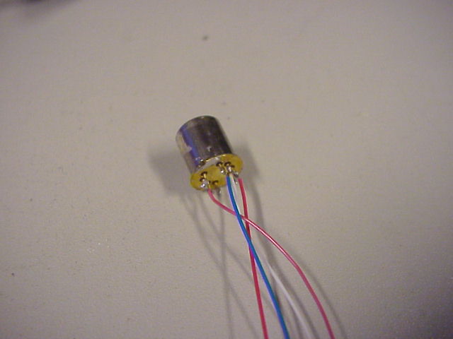
The guilty element was in fact the antenna switch. This is a Teledyne relay, and the TX path was out of order.
Accessing the relay wasn’t easy, as it was deeply hidden inside the aluminium case of the transceiver. I had to unmount both the headset and antenna connectors, in order to remove the board where the relay was soldered…
Thanks to an amateur radio friend, I could get a new relay, and replace it. Hamspirit is still living… Great!
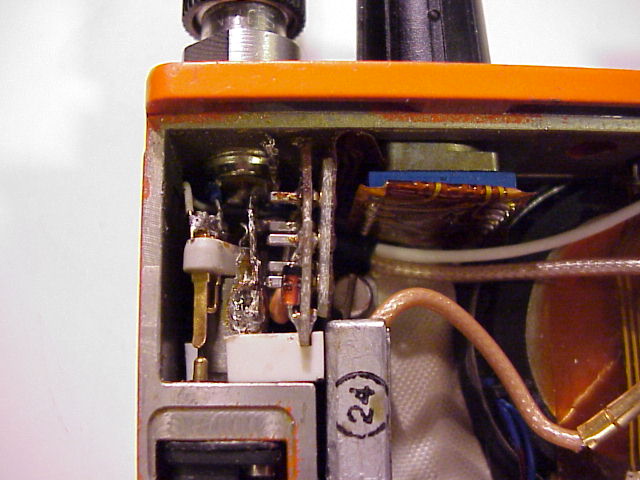
The picture above shows the place where the relay is located. It’s deeply burried under an antenna connector and a headset connector. You have to dismount the headset connector, unsolder the antenna connector and unplug the flexible circuit, in order to remove the printed circuit board where the relay is soldered. Only then you can change the 8 pin relay, and do the whole work backward
Measurement results
| Parameter | Value for Radio A | Value for Radio B | unit |
| TX | |||
| Supply Current @8V | 678 | 670 | mA |
| RF Power | 1 | 1 | W |
| Harmonic 3 level | -49 | -48 | dBm |
| Harmonic 2 level | -56 | -62 | dBm |
| RX (Fmod=1kHz;Deviation=3kHz) | |||
| Supply current (@8V) | 23 | 23 | mA |
| Squelch opens at | -118 | -118 | dBm |
| Minimum dicernable audio (noise floor) | -125 | -125 | dBm |
This is sufficient for the usage I have from these radios. The level of the different harmonics fit with the requirements for amateur radio usage.